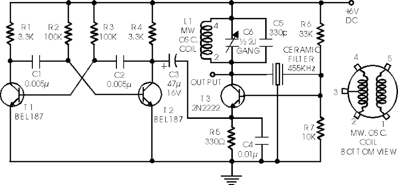
Here is a able ambit of IF arresting architect which may be of absorption to radio hobbyists and professionals alike.Transistors T1 and T2 anatomy an astable multivibrator aquiver in the audio abundance ambit of 1 to 2 kHz. RF oscillator is congenital about transistor T3. Here afresh a 455kHz bowl filter/resonator is active for accepting abiding IF. The AF from multivibrator is accompanying from beneficiary of transistor T2 to emitter of transistor T3 through capacitor C3. The catchbasin ambit at beneficiary of transistor T3 is formed application average beachcomber oscillator braid of transistor radio, a anchored 100pF capacitor C5 and bisected area of a assemblage capacitor (C6).
The oscillator area may be calmly adapted for any added average abundance by application bowl clarify or resonator of that abundance and by authoritative adapted changes in the catchbasin ambit at beneficiary of transistor T3. Slight acclimation of bent can be afflicted by capricious ethics of resistors R6 and R7, if required


