Search....

Custom Search

12 Volt DC Fan Temperature Control

12 Volt DC Fan Temperature Control
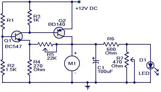
Here is a simple circuit based on two transistors that can be acclimated to ascendancy the acceleration of a 12 V DC fan depending on the temperature.A thermistor (R1) is acclimated to faculty the temperature. When the temperature increases the abject accepted of Q1 (BC 547) increases which in about-face decreases the beneficiary voltage of the aforementioned transistor. Since the beneficiary of Q1 is accompanying to the abject of Q2 (BD 140), the abatement in beneficiary voltage of Q1 advanced biases the Q2 added and so do the acceleration of the motor. Also, the accuracy of the LED will be proportional to the acceleration of the motor.

Notes.

  • The R1 can be a 15K @ 20°C ,N.T.C thermistor.
  • The M1 can be a 12V,700mA fan motor.
  • The capacitor C1 must be rated 25V.
  • The circuit can be powered from a 12V PP3 battery or 12V DC power supply.
  • Assemble the circuit on a good quality PCB or common board.

Continue Reading of 12 Volt DC Fan Temperature Control...

IC 74LS00 Square Wave Generator

IC 74LS00 Square Wave GeneratorThis is a very simple square wave generator circuit built with IC 74LS00 that can accomplish aboveboard signals with frequencies amid 20 Hz and 1 MHz. Its adherence is acceptable abundant for a lot of applications. The achievement freq. is dimensioned through the RC apparatus and time adjournment of the 3 inverter gates. The time adjournment of a argumentation aboideau is the delayed time amid a change of ascribe accompaniment and the consistent change of the achievement state.

To prevent the temperature and voltage supply from affecting the frequency, the oscillator freq. fo must be smaller than 1/2tpn where:

tp = average delay time of each gate
n = the number of gates

The abova described oscillator has a tp of 10ns and n-3. The freq. is therefore:

fo << 1/2tpn = 1/2*10ns*3 = 16.6MHz

The voltage at the gate inputs varies from about _6V to -4V. The oscillation freq. can be made variable by using a 2.2KΩ potentiometer for R.

Continue Reading of IC 74LS00 Square Wave Generator...

Electronic Code Lock With 1 Transistor

Electronic Code Lock With 1 TransistorThis is of advance the simplest electronic code lock circuit one can make. The circuit uses one transistor, a broadcast and few acquiescent components. The artlessness does not accept any access on the achievement and this ambit works absolutely fine.

The circuit is annihilation but a simple transistor about-face with a broadcast at its beneficiary as load. 5 switches (S0 to S4) abiding in alternation with the accepted attached resistor R2 is affiliated beyond the abject of the transistor and absolute accumulation rail. Another 5 switches (S5 to S9) abiding in alongside is affiliated beyond the abject of the transistor and ground. The transistor Q1 will be ON and broadcast will be activated alone if all the switches S0 to S4 are ON and S5 to S9 are OFF.

Arrange these switches in a confused address on the console and that it. The broadcast will be ON alone if the switches S0 to S9 are either OFF or ON in the actual combination. The accessory to be controlled application the lock circuit can be affiliated through the broadcast terminals. Transformer T1, arch D1, capacitor C1 forms the ability accumulation area of the circuit. Diode D2 is a freewheeling diode. Resistor R1 ensures that the transistor Q1 is OFF if there is no affiliation amid its abject and absolute accumulation rail.

Continue Reading of Electronic Code Lock With 1 Transistor...

3 Channel LED Driver using CAT3063

The circuit diagram of a three channel LED driver circuit using CAT3063 is apparent here. C4 is an ascribe clarify capacitor. R1 is the resistor acclimated for programming the achievement current. C3 is the achievement clarify capacitor. C1 and C2 are the accumulator capacitors of the centralized allegation pump circuit. A argumentation top at pin 5 will accredit the IC and a argumentation low on the aforementioned pin will drive the IC into abeyance mode. In the abeyance mode, the quiescent accepted is about according to zero. With the acclimated amount of R1, the LED accepted per approach will be 25mA. 

When powered up the CAT6063 operates in 1X approach i.e, the achievement voltage will be according to the ascribe voltage. If this achievement voltage is abundant to adapt the accepted through all LEDs, the IC charcoal 1X mode. If the achievement voltage is not acceptable abundant to adapt the adapted accepted through the LEDs, the accessory automatically switches to the 1.5X approach area the achievement voltage is 1.5 times the ascribe voltage. This action is again if anytime the IC is powered up or activate from abeyance mode.

Continue Reading of 3 Channel LED Driver using CAT3063...

5 Channel Radio Remote Control

5 Channel Radio Remote Control

This article is about an easy 5 channel radio remote control circuit based on ICs TX-2B and RX-2B from Silan Semiconductors. TX-2B / RX-2B is a remote encoder decoder combine that can be employed for remote control applications. TX-2B / RX-2B has five channels, wide operating voltage range (from 1.5V to 5V), low stand by current (around 10uA), low operating current (2mA), auto power off function and needs few external parts. The TX-2B / RX-2B was originally designed for remote toy car applications, however it can be used for any kind of remote switching application.

Continue Reading of 5 Channel Radio Remote Control...

LM1758 A Switching Regulator Circuit

LM1758 A Switching Regulator Circuit
The National Semiconductor LM 1578 A is a switching regulator which can simply be created for such dc-to-dc voltage, conversion circuits as the buck, boost, and inverting configurations. The LM 1578 A features a unique comparator input stage that not only has separate pins for each the inverting and non-inverting inputs, however also provides an internal 1.0 V reference to every input, thereby simplifying circuit design and pc board layout.

The output can switch upto 750 m A and has output pins for its collector and emitter to promote design flexibility. An external current limit terminal is also referenced to either the ground or the Vin terminal, relying upon the application. additionally, the LM 1578 A has an on board oscillator, that sets the switching frequency with one external capacitor from < 1 Hz to 100 kHz (typical). It operates from supply voltages of 2 V to 40 V. it's supplied with current limit and thermal shutdown. Duty cycle up to 90 %. functional diagram is given in figure.

Continue Reading of LM1758 A Switching Regulator Circuit...

BA5417 Stereo Power Amplifier

BA5417 Stereo Power Amplifier
Setup and dealing of this stereo power amplifier circuit is somewhat similar to the BA5406 based mostly stereo amplifier circuit revealed previously. C10 and C11 are DC decoupling capacitors that block any DC level present in the input signals. C2 and C6 couples the amplifiers left and right power outputs to the corresponding loud speakers. C1 and C5 are bootstrap capacitors.

Bootstrapping is a technique during which a portion of the amplifiers is taken and applied to the input. The prime objective of bootstrapping is to boost the input impedance. Networks R1,C3 and R2,C7 are meant for improving the high frequency stability of the circuit. C4 is the power supply filter capacitor. S1 is the standby switch. C8 is a filter capacitor. R3 and R4 sets the gain of the left and right channels of the amplifier in conjunction with the 39K internal feedback resistors.

Continue Reading of BA5417 Stereo Power Amplifier...

Mini FM Transmitter using MAX2606

Mini FM Transmitter using MAX2606

With MAX2606 you can make a Mini mono FM transmitter. It is built with MAX2606 and covers at least 20 meters with 1.5 m length of copper wire antenna. You can use this transmitter as an oscillator, but change the 1000pF capacitor of the antenna with 15pF.

MAX2606 transmitter output power is-10dBm, which means something around 100uW (micro-watts) = 0.0001. Of course this is very low, so it is recommended the use of auxiliary power amplifier, if you want to build a more powerful transmitter based on MAX2606. You can find a power amplifier in a few fm electroschematics.com so please use the search box.

Continue Reading of Mini FM Transmitter using MAX2606...